Modifying a Xiaomi Zigbee Button

Posted on 2019-02-05 in makes

In late 2017, i was fiddling around trying to teach myself fusion 360, and accidentally found myself designing a giant red button. I didn't really have a use for it at the time, so i added a microswitch, printed it out, and had a random giant button sat around in my office, mostly getting in the way.

The Button

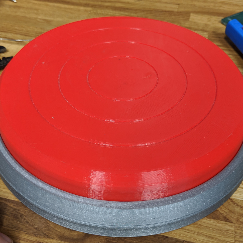
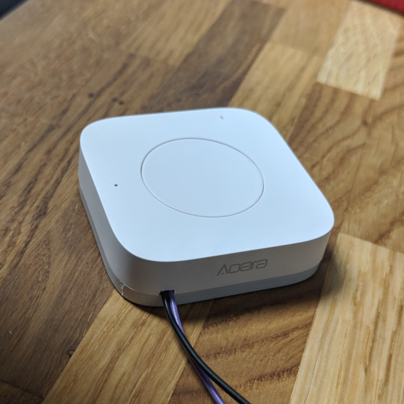
Fast forward a bit, and i've implemented a home automation system with a zigbee network, and a £5 Xiaomi Aqara Zigbee button. This button is around 5cm x 5cm, battery powered, and as far as I can tell lasts for infinity time from a single coin cell. I can't help but think though... what if it was giant instead?

Inside

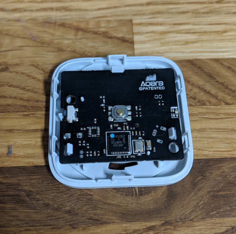
Step one was of course to open up my nice new button. Quick attack of the spudger had the case popped open and ready for a bit of probing. Now, if i was designing this board, i'd probably duplicate the button out to a test pad or pin header somewhere. Luckily the engineers at xiaomi appear to agree with me, and the header in the top right is connected directly across the input switch, score!

Wires to the front of the board Wires to the back of the board

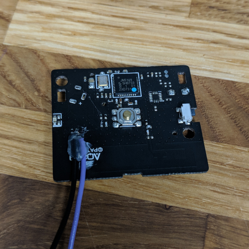
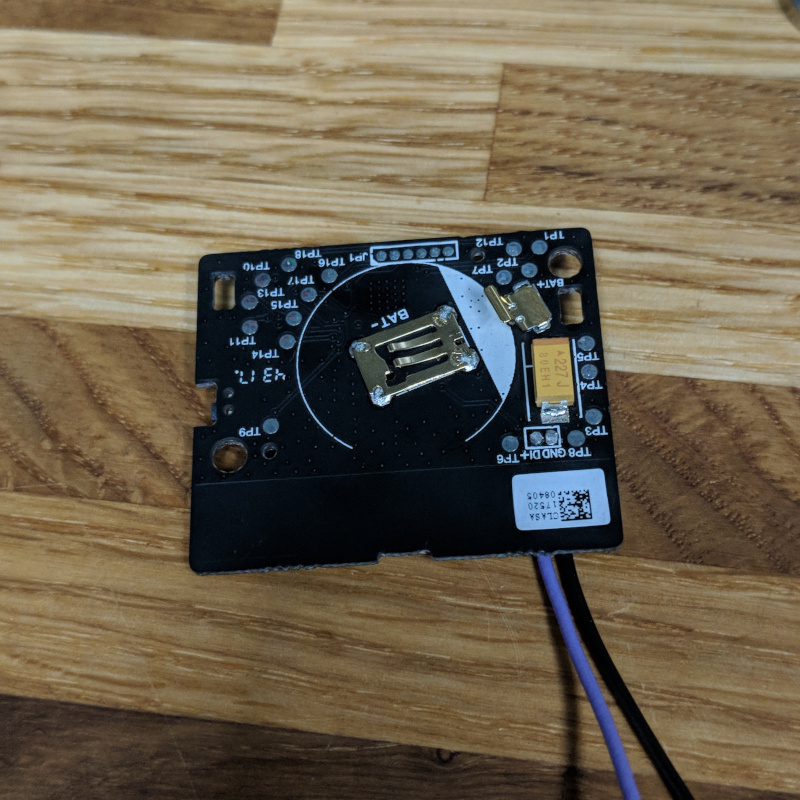
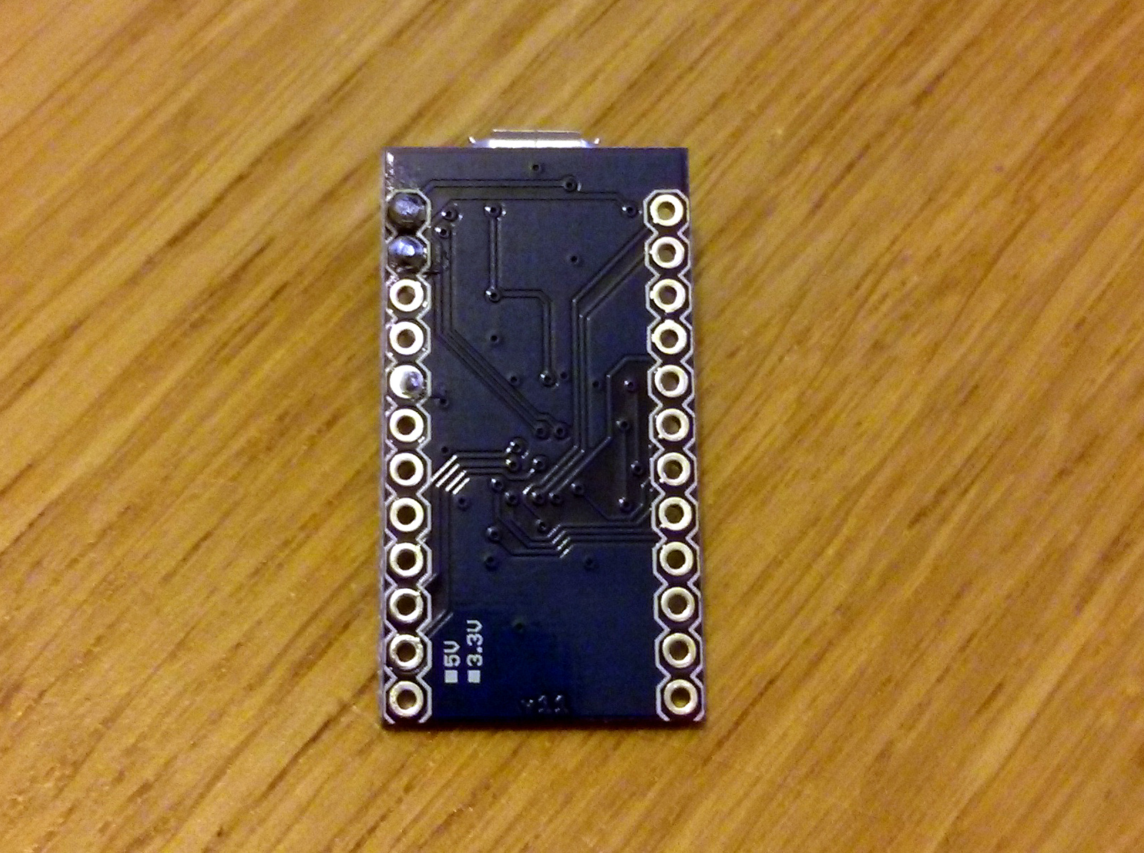
I soldered a couple of wires to the board, and added some hotglue to provide a minimum of strain relief. As an aside, look at all those lovely labelled test points on the back of the board, this could make a fairly nice development board for the NXP zigbee microcontroller.

Wires to the microswitch

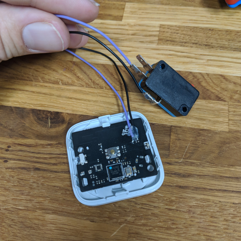
I wired in a microswitch to the other end of my cables, and pressing the microswitch triggers the button, yay!

Reassembled

A small amount of poking with a scalpel let me remove enough plastic from the corner of the case to feed the wire through and assemble the Aqara button.

Fitted into button

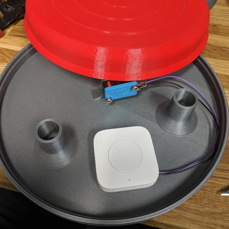
Assemble into the button, and a little bit of hacking to make an automation in homeassistant, and we have a light switch for the 3d printer light!


Project - Lil' Buggers

Posted on 2014-05-12 in makes

Lil Buggers

We like to do occasional workshops at the Hackspace, so when we were asked to make something 'bug themed' for a workshop, we jumped on it.   The first thought we had was to make up some bug-shaped PCBs with a circuit to flash LEDs, and run a soldering workshop.  When we found out the workshop was a week away, we panicked a little, as that's not really enough time to get PCBs manufactured at a sensible price.

We decided instead to make little laser cut bugs with LED eyes, as they can be made with easily available materials, and infinitely customised.

Step one was to choose a material.  Our first experiments were with acrylic.  I whipped up some designs for 'joints', which would friction fit onto the side or top of a 'body'.  I attached these to a curved path in inkscape for the legs, and bug #0 was born!

Bug 0

Bug #0 had a couple of issues, mainly due to the material choice.  Acrylic thicknesses can be a bit variable, the tolerance can be as wide as ±10%, and it is fairly brittle.  the combination of these two issues caused at least one broken leg (hence #0 having 5 legs!).

We decided to have a go at laser MDF instead.  Laser MDF is basically MDF made with a glue that is less harmful to people and laser cutters than regular MDF.  It has the advantage of being very dimensionally accurate (our 3.2mm MDF was measured at 3.21mm), and having a bit of bend before it breaks.

Bug 1

Bug #1 was born.  It assembled a lot easier than #0, and has cool looking scorched edges.   At this point I started designing some add-on parts to allow attendees to customise their bugs, including wings, tails, hairy legs, and mandibles.

The only issue with #1 was losing the wide range of colours available from acrylic.  However, I had a flash of inspiration, and gave a sheet of laser MDF a light coat of red spraypaint.   This dries fast, and gives an awesome splash of colour.

Bug 2   
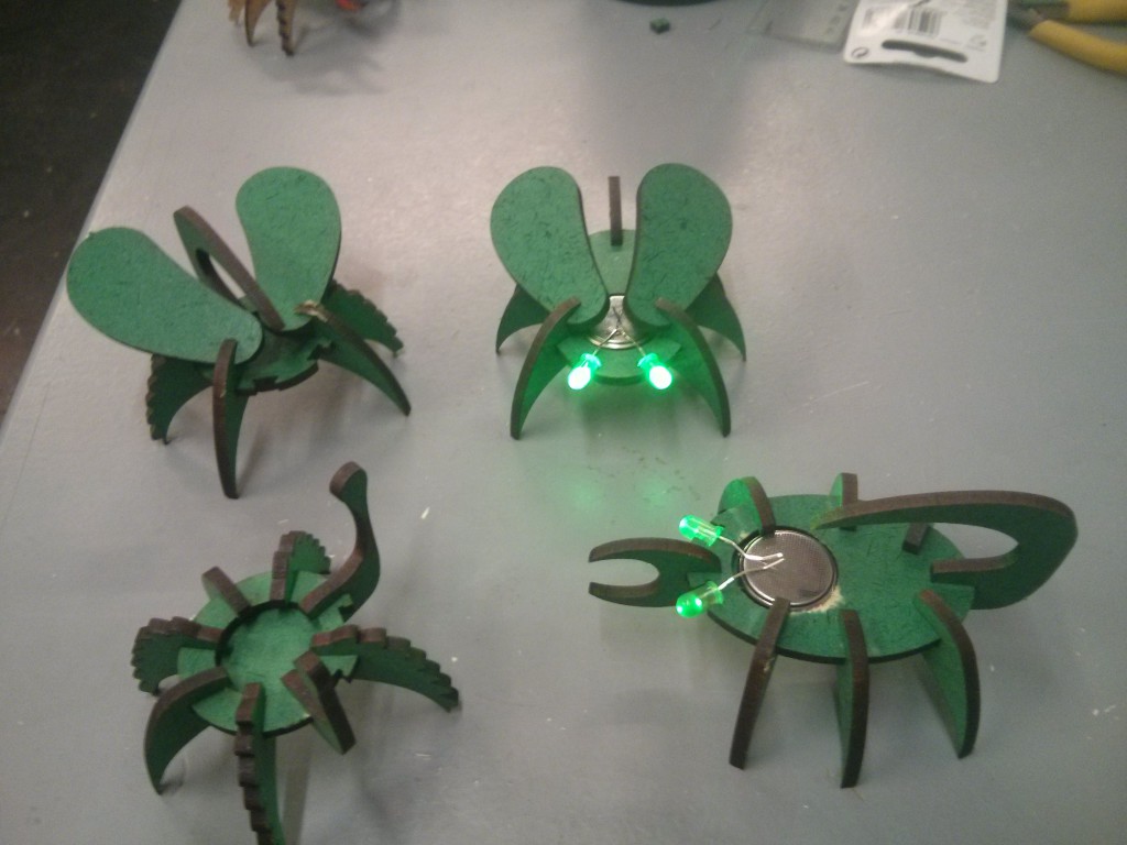
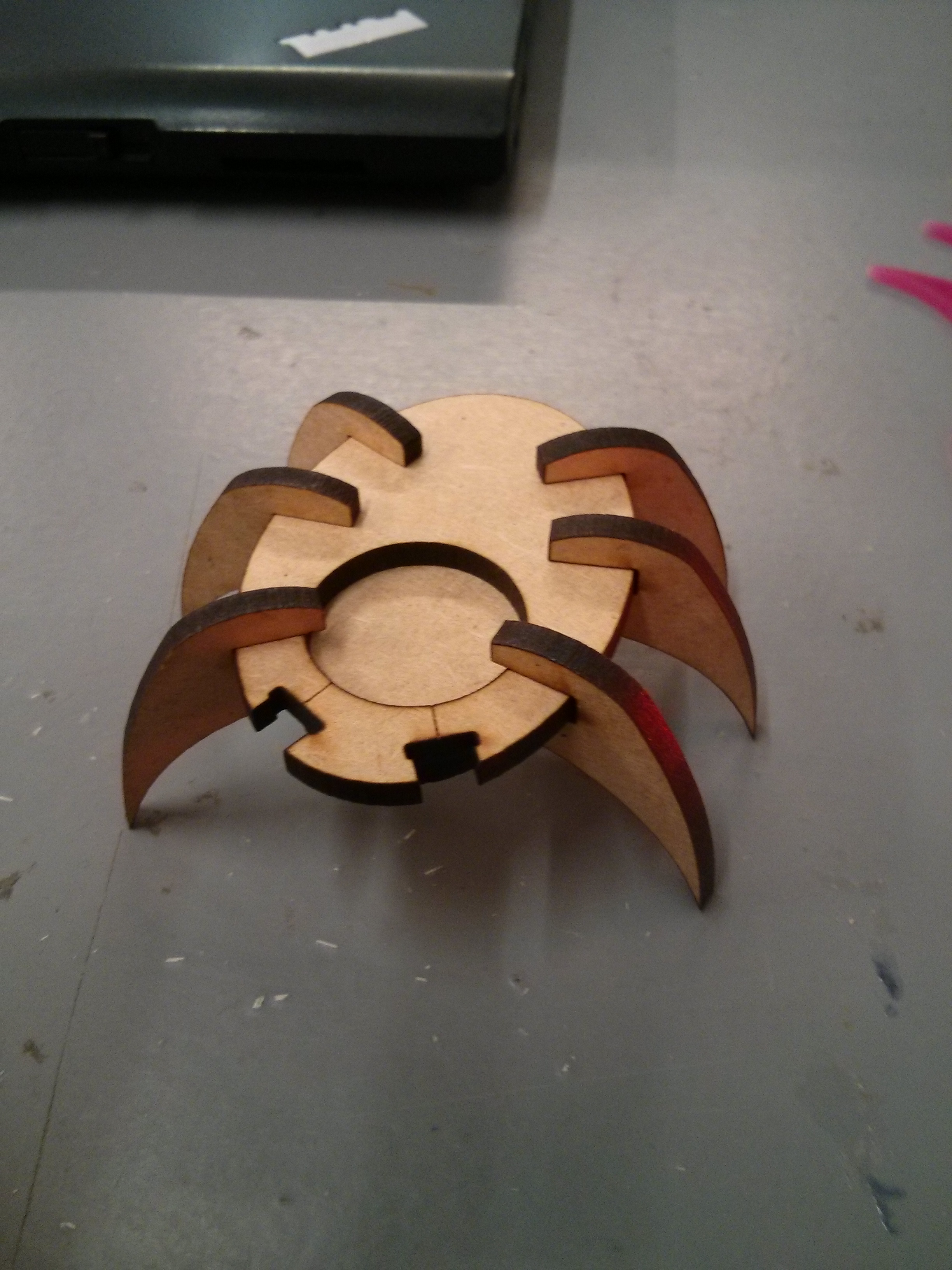
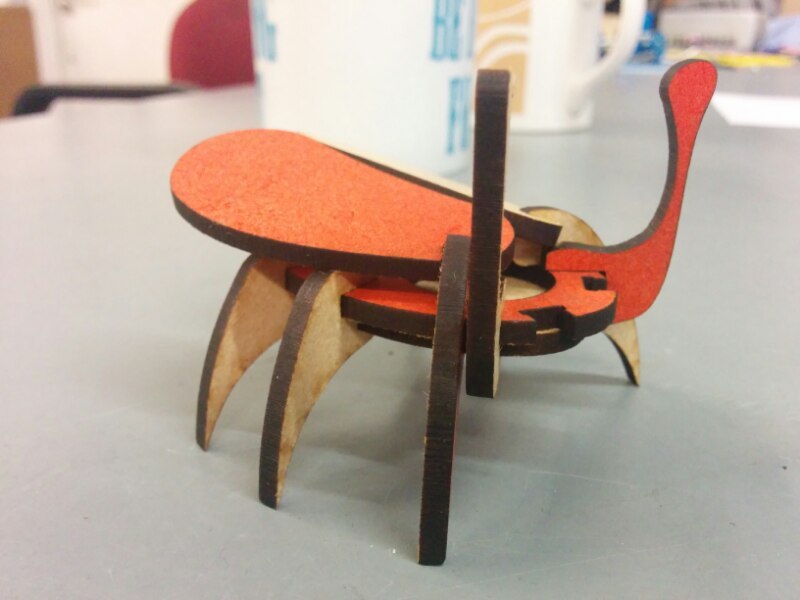
Bug #2 is alive!  This time sporting a lovely pair of wings and some antennae. #2 was done with just one side of the wood painted, which gives a cool effect. depending on what side of the bug you're looking at.

Then things got a bit silly...

Bugs

We now have a swarm of these delightful Lil' Buggers invading the hackspace.  With a magnet and a dab of hotglue they'll stick to anything metallic, and their LED eyes last for a couple of days on a coin cell.


45 Minute Project - £4.10 XBMC Remote Receiver

Posted on 2014-03-01 in makes

I'm a big fan of XBMC, and have an Ouya running XBMC set up in my lounge, streaming from my NAS. I normally use XBMC remote on my phone for controlling it, but this gets annoying when the phone is on charge, or I'm using it for something else.

I noticed that the majority of my TV remote is completely unused when the TV is in HDMI mode, and had a bit of a lightbulb moment!

Remote 
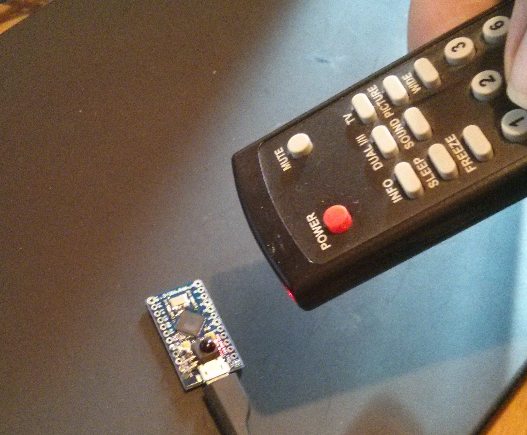
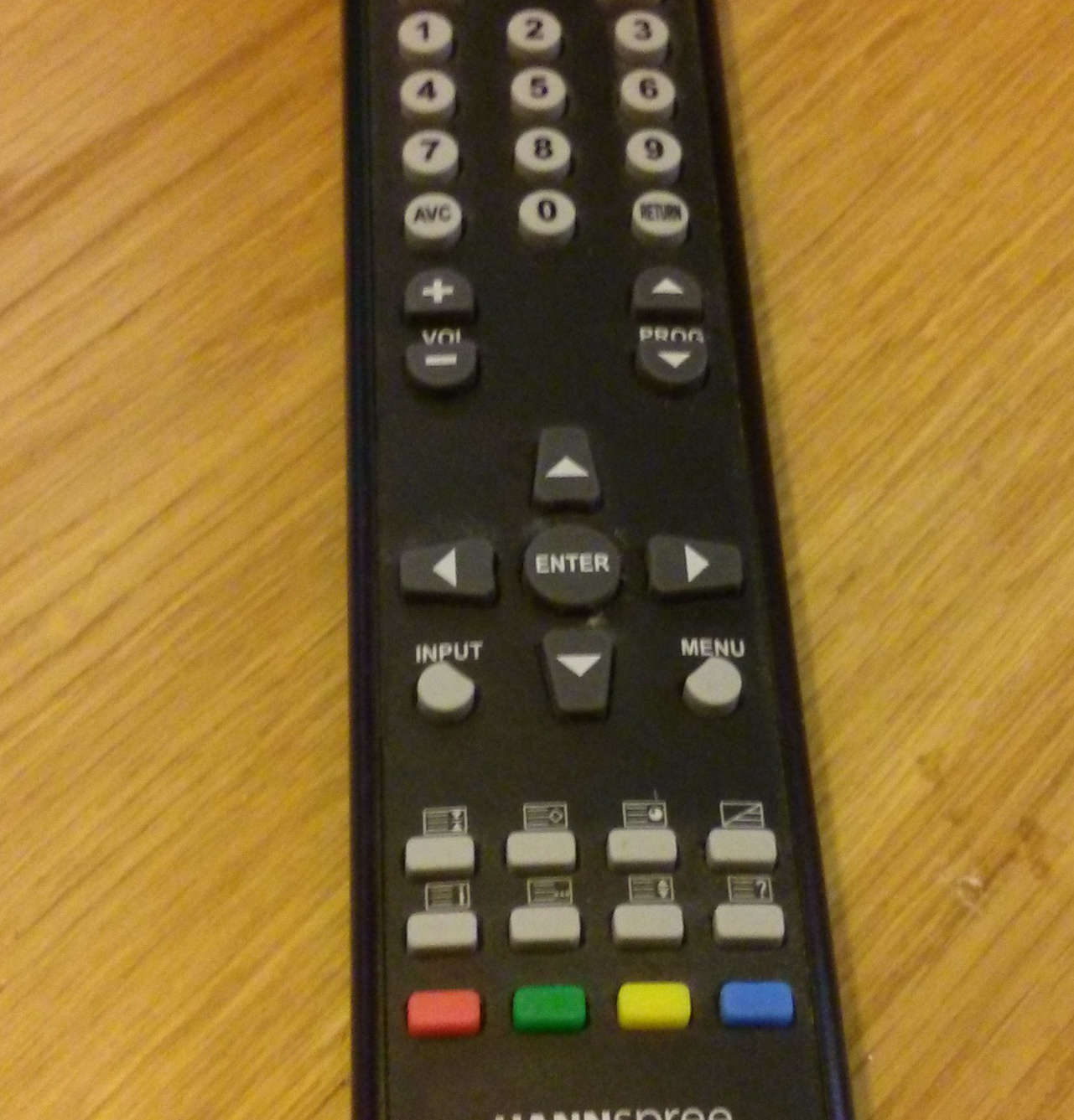
Almost none of these buttons are used!

I already had an Arduino Pro Micro (£3) lying about i'd bought for testing out as an upgrade path for the minimus based projects i've been playing with.  It is leonardo compatible, small, cheap and pretty easily available.  I added an IR Receiver (£1.10) to the weekly Hackspace Farnell order to complete the parts list.

The pinout of the IR receiver makes it very easy to connect to the pro micro, using the RAW (VUSB), GND, and A3 pins.  I just bent the OUT pin (pin 1) on the receiver to the left a bit as follows:

Front Back   
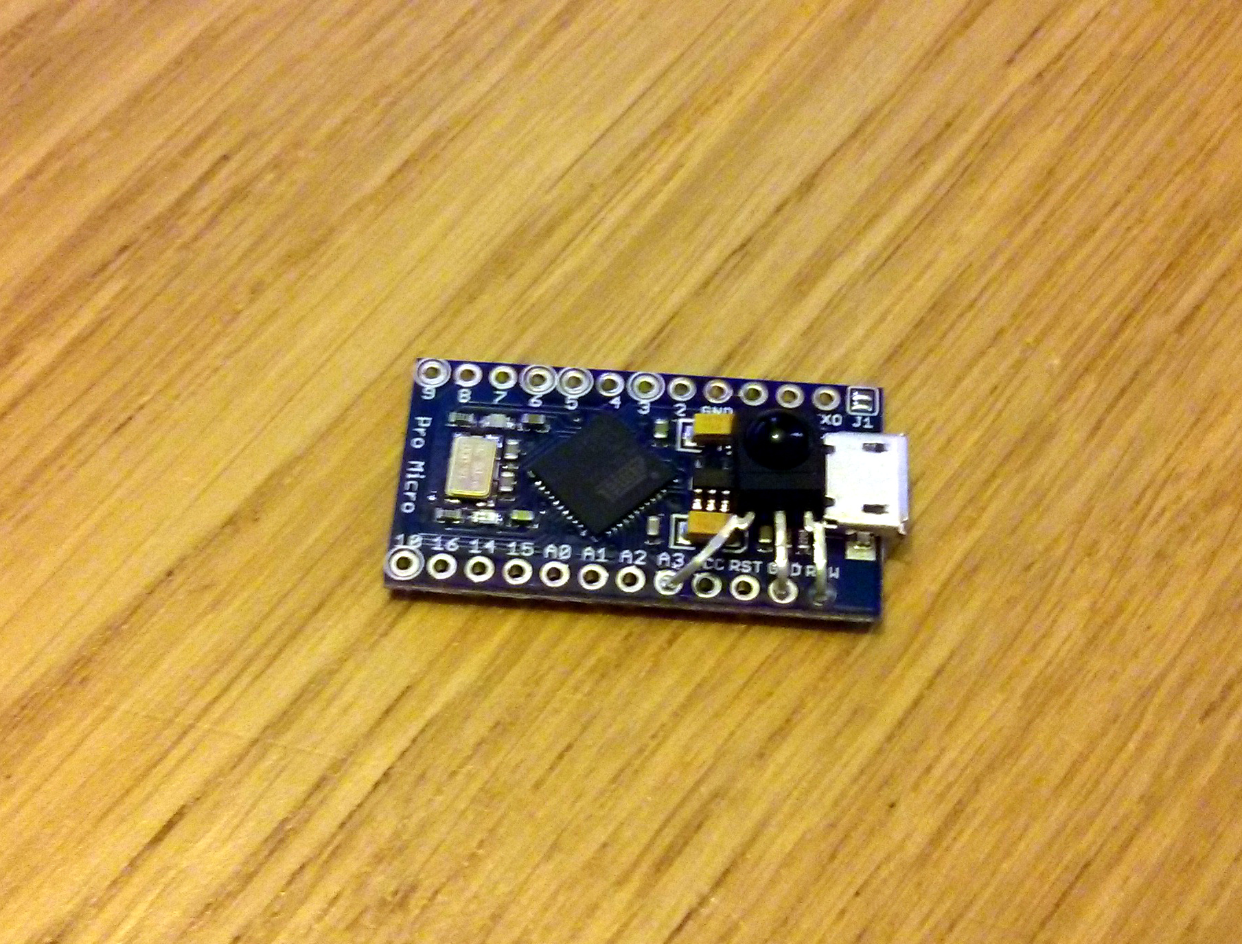
The body of the receiver fits perfectly behind the USB plug, flat against the voltage regulator.  I used the IRremote arduino library to grab data from the remote using the IRrecvDemo sketch and mushed some buttons:

1
8B452ADFFFFFFFFFFFFFFFF8B410EFFFFFFFFFFFFFFFFFFFFFFFFF8B4D22DFFFFFFFF8B4926DFFFFFFFFFFFFFFFF

My remote uses 0xFFFFFFFF as a 'key repeat' code, about every 200ms when the button is held down. I found that in practice I had to ignore the first of these, as it was repeating way too fast and doing double presses.

I tweaked the IRrecvDemo sample code, added in a bit of keyboard and came up with some working code:

 1
 2
 3
 4
 5
 6
 7
 8
 9
10
11
12
13
14
15
16
17
18
19
20
21
22
23
24
25
26
27
28
29
30
31
32
33
34
35
36
37
38
39
40
41
42
43
44
45
46
47
48
49
50
51
52
53
54
55
56
57
58
59
60
61
62
63
64
65
66
67
68
#include IRrecv
int RECV_PIN = A3;

IRrecv irrecv(RECV_PIN);
decode_results results;

int key;
int count;

void setup()
{
  irrecv.enableIRIn(); // Start the receiver
}

void loop() {
  if (irrecv.decode(&results)) {
    switch (results.value)
    {
      case 0x8B452AD: // up
        key = KEY_UP_ARROW;
        count = 0;
        break;
      case 0x8B410EF: // right
        key = KEY_RIGHT_ARROW;
        count = 0;
        break;
      case 0x8B4D22D: // down
        key = KEY_DOWN_ARROW;
        count = 0;
        break;
      case 0x8B4D02F: // left
        key = KEY_LEFT_ARROW;
        count = 0;
        break;
      case 0x8B4926D: // enter
        key = KEY_RETURN;
        count = 0;
        break;
      case 0x8B412ED: // red
        key = KEY_BACKSPACE;
        count = 0;
        break;
      case 0x8B4B24D: // green
        key = ' ';
        count = 0;
        break;
      case 0x8B44AB5: // yellow
        key = KEY_ESC;
        count = 0;
        break;
      case 0x8B450AF: // blue
        key = 's';
        count = 0;
        break;
      case 0xFFFFFFFF:
        count++;
        break;
      default:
        key = -1;
        break;
    }

    if ((key != -1) && (count!=1)) // if count = 1, it is the first key repeat, so ignore it.
      Keyboard.write(key);

    irrecv.resume(); // Receive the next value
  }
}

Total cost £4.10, total time 45 minutes. Sorted!

Zappp


Minimus Pin Functions

Posted on 2012-02-13 in misc

Minimus Pin Functions

Whipped up this quick cheat sheet with all the different functions each minimus pin can perform.


Speak and Spell - Keyboard Matrix

Posted on 2011-01-27 in misc

Speak and Spell

Tonight i spent some time at Hackspace Manchester reverse engineering the keyboard matrix on our speak and spell, in preparation for hooking it up to an MBED.  Since nobody else has released this information (as far as i can tell), here is the pinout:

pin 3 4 5 6 7 8 9 10
1 u k off a f ? p z
2 v l go b g & q `
11 w m < c h ??? r #
12 x n " d i :) s /
13 y o _ e j on t return

This means that when the 'off' button is pressed, for example, pin 1 and pin 5 will be connected together.

To read a matrix keyboard like this, we write some code that steps through the 'down' set of pins (1, 2, 11, 12, 13), holding them low one at a time, then checks each of the other pins (3-10) to see if anything is being held low. If so, we perform a lookup on the table above.