Automatically starting a Python script at boot on Raspbian Jessie

Posted on 2016-07-06 in sysadmin

As part of the Hackspace Manchester door control system, we have a raspberry pi running a little script that checks scanned cards against a database of members and opens the door if the card is known.  This has been humming along happily for around 3 years now, until recently it stopped updating card IDs when they were changed via the webui.

This led to a bit of a bug hunt, concluding with the fact the version of openssl on raspbian wheezy was waaaaay out of date, and we'd recently updated our members system to disable insecure cyphers on the HTTPS protocol.  We fixed it by upgrading to jessie, which as a side effect completely killed the auto-start of the door opening programme. Yay?

So.  Jessie.  Systemd.  Init system is a a bit different from sysvinit, but on the whole i find it a lot more sensible.  We want to run a script as the user 'alfred' (the door entry service user).  We also want to wait until the system is booted, and the serial port is available.

My script is called alfred, so i create the following file in /lib/systemd/system/alfred.service

 1
 2
 3
 4
 5
 6
 7
 8
 9
10
11
12
[Unit]
Description=alfred
After=dev-ttyAMA0.device multi-user.target

[Service]
Type=idle
ExecStart=/home/alfred/FRED/fred/fred.py
WorkingDirectory=/home/alfred/FRED/fred/
User=alfred

[Install]
WantedBy=multi-user.target

The After= says what services need to be up before this is run. In this case, it wants ttyAMA0 to be available, along with multi-user (this is the point where you could normally log in)

ExecStart= specifies the script I will be running, WorkingDirectory= is the directory to run the thing from (as i use relative paths in my python script, i need to set this), and User= says what unprivileged user to run the script as, since you don't want to be running random things as root if at all possible!

WantedBy= says that this should be started at the same time as multi-user.target, so at the end of the boot process, at the point you could normally log in.

We can then set up our new service to start on boot, and run it for the first time:

 1
 2
 3
 4
 5
 6
 7
 8
 9
10
11
12
13
$ systemctl enable alfred
$ systemctl start alfred
No errors, so lets check the status:
$ sudo systemctl status alfred
● alfred.service - alfred
Loaded: loaded (/lib/systemd/system/alfred.service; enabled)
Active: active (running) since Wed 2016-07-06 16:42:59 BST; 30min ago
Main PID: 709 (fred.py)
CGroup: /system.slice/alfred.service
└─709 /usr/bin/python /home/alfred/FRED/fred/fred.py
Jul 06 16:42:59 alvin systemd[1]: Starting alfred...
Jul 06 16:42:59 alvin systemd[1]: Started alfred.
Jul 06 16:43:01 alvin fred.py[709]: 2016-07-06 16:43:01,577 FRED 0.7

Looks good, service is started, and we're getting some log output from it. Reboot to check everything comes up correctly and you're done!

... Though i wasnt. One gotcha I ran into is that because of the way raspbian's networking is set up, you can't get systemd to wait until after you have a network connection configured before starting the script (it will wait until the networking service is started, but not wait for the network to actually be up). This can be worked around pretty easily by setting the "Wait for network on boot" option in raspi-config, which will pause the whole boot process until it gets a DHCP lease.


Project - Lil' Buggers

Posted on 2014-05-12 in makes

Lil Buggers

We like to do occasional workshops at the Hackspace, so when we were asked to make something 'bug themed' for a workshop, we jumped on it.   The first thought we had was to make up some bug-shaped PCBs with a circuit to flash LEDs, and run a soldering workshop.  When we found out the workshop was a week away, we panicked a little, as that's not really enough time to get PCBs manufactured at a sensible price.

We decided instead to make little laser cut bugs with LED eyes, as they can be made with easily available materials, and infinitely customised.

Step one was to choose a material.  Our first experiments were with acrylic.  I whipped up some designs for 'joints', which would friction fit onto the side or top of a 'body'.  I attached these to a curved path in inkscape for the legs, and bug #0 was born!

Bug 0

Bug #0 had a couple of issues, mainly due to the material choice.  Acrylic thicknesses can be a bit variable, the tolerance can be as wide as ±10%, and it is fairly brittle.  the combination of these two issues caused at least one broken leg (hence #0 having 5 legs!).

We decided to have a go at laser MDF instead.  Laser MDF is basically MDF made with a glue that is less harmful to people and laser cutters than regular MDF.  It has the advantage of being very dimensionally accurate (our 3.2mm MDF was measured at 3.21mm), and having a bit of bend before it breaks.

Bug 1

Bug #1 was born.  It assembled a lot easier than #0, and has cool looking scorched edges.   At this point I started designing some add-on parts to allow attendees to customise their bugs, including wings, tails, hairy legs, and mandibles.

The only issue with #1 was losing the wide range of colours available from acrylic.  However, I had a flash of inspiration, and gave a sheet of laser MDF a light coat of red spraypaint.   This dries fast, and gives an awesome splash of colour.

Bug 2   
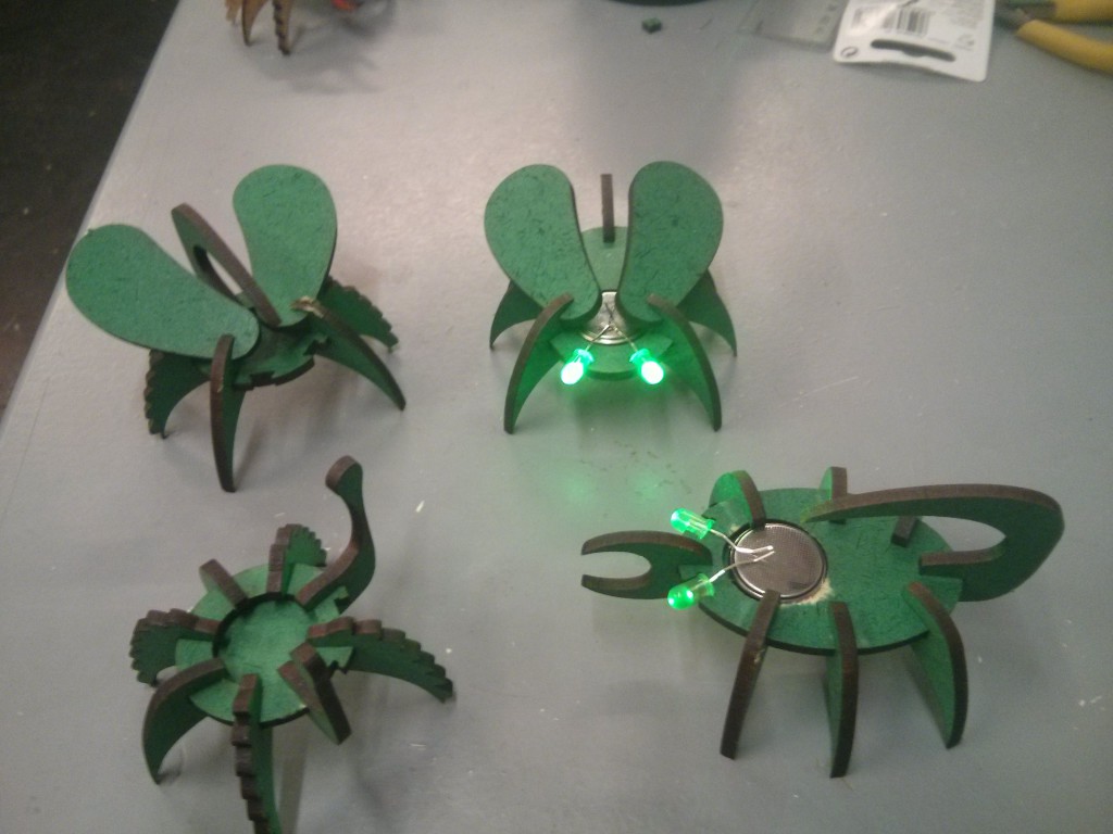
Bug #2 is alive!  This time sporting a lovely pair of wings and some antennae. #2 was done with just one side of the wood painted, which gives a cool effect. depending on what side of the bug you're looking at.

Then things got a bit silly...

Bugs

We now have a swarm of these delightful Lil' Buggers invading the hackspace.  With a magnet and a dab of hotglue they'll stick to anything metallic, and their LED eyes last for a couple of days on a coin cell.


45 Minute Project - £4.10 XBMC Remote Receiver

Posted on 2014-03-01 in makes

I'm a big fan of XBMC, and have an Ouya running XBMC set up in my lounge, streaming from my NAS. I normally use XBMC remote on my phone for controlling it, but this gets annoying when the phone is on charge, or I'm using it for something else.

I noticed that the majority of my TV remote is completely unused when the TV is in HDMI mode, and had a bit of a lightbulb moment!

Remote 
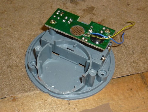
Almost none of these buttons are used!

I already had an Arduino Pro Micro (£3) lying about i'd bought for testing out as an upgrade path for the minimus based projects i've been playing with.  It is leonardo compatible, small, cheap and pretty easily available.  I added an IR Receiver (£1.10) to the weekly Hackspace Farnell order to complete the parts list.

The pinout of the IR receiver makes it very easy to connect to the pro micro, using the RAW (VUSB), GND, and A3 pins.  I just bent the OUT pin (pin 1) on the receiver to the left a bit as follows:

Front Back   
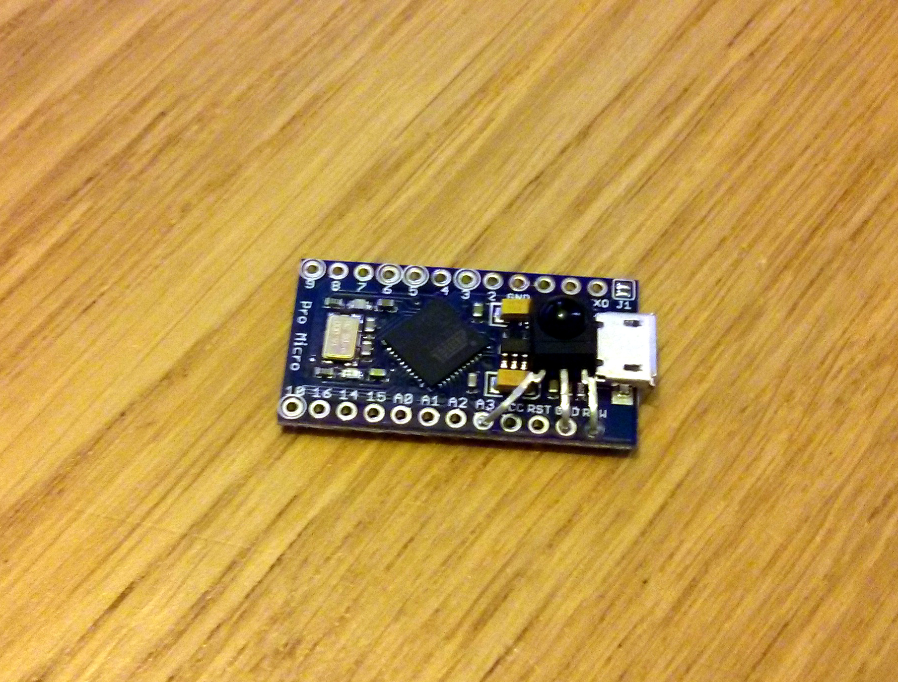
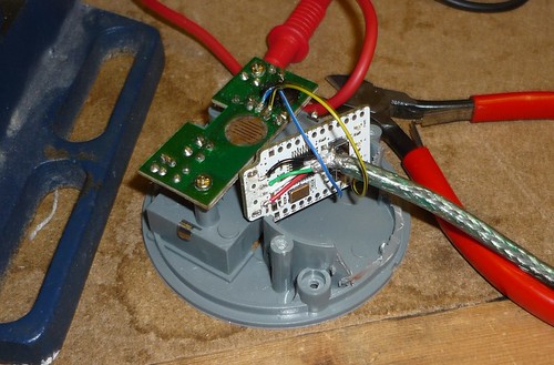
The body of the receiver fits perfectly behind the USB plug, flat against the voltage regulator.  I used the IRremote arduino library to grab data from the remote using the IRrecvDemo sketch and mushed some buttons:

1
8B452ADFFFFFFFFFFFFFFFF8B410EFFFFFFFFFFFFFFFFFFFFFFFFF8B4D22DFFFFFFFF8B4926DFFFFFFFFFFFFFFFF

My remote uses 0xFFFFFFFF as a 'key repeat' code, about every 200ms when the button is held down. I found that in practice I had to ignore the first of these, as it was repeating way too fast and doing double presses.

I tweaked the IRrecvDemo sample code, added in a bit of keyboard and came up with some working code:

 1
 2
 3
 4
 5
 6
 7
 8
 9
10
11
12
13
14
15
16
17
18
19
20
21
22
23
24
25
26
27
28
29
30
31
32
33
34
35
36
37
38
39
40
41
42
43
44
45
46
47
48
49
50
51
52
53
54
55
56
57
58
59
60
61
62
63
64
65
66
67
68
#include IRrecv
int RECV_PIN = A3;

IRrecv irrecv(RECV_PIN);
decode_results results;

int key;
int count;

void setup()
{
  irrecv.enableIRIn(); // Start the receiver
}

void loop() {
  if (irrecv.decode(&results)) {
    switch (results.value)
    {
      case 0x8B452AD: // up
        key = KEY_UP_ARROW;
        count = 0;
        break;
      case 0x8B410EF: // right
        key = KEY_RIGHT_ARROW;
        count = 0;
        break;
      case 0x8B4D22D: // down
        key = KEY_DOWN_ARROW;
        count = 0;
        break;
      case 0x8B4D02F: // left
        key = KEY_LEFT_ARROW;
        count = 0;
        break;
      case 0x8B4926D: // enter
        key = KEY_RETURN;
        count = 0;
        break;
      case 0x8B412ED: // red
        key = KEY_BACKSPACE;
        count = 0;
        break;
      case 0x8B4B24D: // green
        key = ' ';
        count = 0;
        break;
      case 0x8B44AB5: // yellow
        key = KEY_ESC;
        count = 0;
        break;
      case 0x8B450AF: // blue
        key = 's';
        count = 0;
        break;
      case 0xFFFFFFFF:
        count++;
        break;
      default:
        key = -1;
        break;
    }

    if ((key != -1) && (count!=1)) // if count = 1, it is the first key repeat, so ignore it.
      Keyboard.write(key);

    irrecv.resume(); // Receive the next value
  }
}

Total cost £4.10, total time 45 minutes. Sorted!

Zappp


3D printing - Bandsaw Fence

Posted on 2013-03-21 in makes

I spent some time earlier in the week getting the bandsaw at Hackspace Manchester working, so now its cutting again!  The main problem with the bandsaw is cutting straight, as it was an ebay purchase it diddnt come with a fence, so there was nothing to run the cut material against.  This model of bandsaw hasnt been made in around 30 years, so trying to buy a new one will be impossible, and ebay is too much hard work.

Though we do have a 3d printer... and a workshop.  Idea!

Step one was to have a look at the bandsaw.  It has a channel running along the front , so I took some measurements to see what I was working with.

channel paper

So, i had the measurements, it was time to take to my CAD software and design something to fit in the channel.  My choice for this is OpenSCAD.  I used it to first create the shape of the channel, then to carve this shape out of a block.

openscad1 openscad2

I extruded this to a few mm wide, then printed it to test.  There was a bit of tweaking needed to get it to fit exactly, so i ended up doing 4 iterations with the sizes tweaked slightly.

testpieces

testprint test

Once i had one that fitted, i printed it out extruded to 20mm to check it would fit and slide correctly.

testfits

It did, so i moved onto designing the actual fence.  Step one was to cut some aluminium extrusion to size, and measure it.  A month or so ago I had managed to womble a nice straight piece of 16mm x 16mm  3.2mm thick L channel, which was pretty much the perfect size.  I cut this to size, and modelled it in openscad.

cad

The actual cad modelling took a couple of hours of tweaking, but i the above picture shows the basic steps.

First off i extruded my clamp to 50mm wide, and added a wedge to the side of it.  50mm gives enough width for it to sit in the runner, and counteract twisting force from the back of the fence being pushed on.  The wedge is to give support to the top part of the L channel.

Second, I added two captive nuts and holes for M5 bolts.  Mainly because we have a massive bag of M5 hex-head bolts that are perfect for printed thumbscrews. Theoretically i could have threaded into the ABS directly, but i felt this wouldnt last, so embedding a nut seemed like the best option.

Third, i carved out the hole for the L channel.  This leaves a bit of an odd shaped unsupported piece, which may be weak. Because this piece will be in the channel, i decided to leave it, as it'll make measuring up on the built-in ruler more accurate.

Lastly, i added some pilot holes for attaching the aluminium to the 3d printed part.  i decided to use 3mm x 12mm self tapping screws for this, because i had them on hand, and they can be countersunk fairly easily.

printed

I test-assembled the whole thing in the vice, it fitted nicely in the channel, so it was ready for connecting together.  I marked, center punched, drilled and countersunk the holes for the 3 screws that hold the whole thing together.  Add some screws and we're sorted!

fits

Of course, i had to do a test cut at this point, so some of the scrap acrylic pile was chopped into little strips.

cutting

Woohoo, it worked!  All it needed to be complete is some knobs.  So i headed over to thingiverse to find a knob that'll fit nicely over an m5 nut... and found nothing useful.  No worries, i just OpenSCADdded one up.

knob

finished

So there it is, a useful thing i've made on the 3d printer that wasnt a part for a 3d printer!

Source files (stl, openscad) are available on My GitHub 


The PANIC Button

Posted on 2012-02-19 in makes

Ok, bit of explanation first.  We have an iMac set up as a 'democratic jukebox' at Hackspace Manchester.  The idea being that anyone can put music on it, and it plays the entire library on shuffle during our hack sessions for a bit of background music.

The problem is, of course, some people have an... odd taste in music, so sometimes the jukebox ends up flipping between Aqua and Cannibal Corpse for ten minutes, and the horror of this was just too much!

Enter the PANIC button.

PANIC

The button uses a minimus board. The minimus is a carrier for the AT90USB162, an AVR microcontroller with onboard USB hardware, which means it can be programmed to show up as any USB device.  Before getting the button I modified one of the pieces of LUFA demo software, a media keyboard, and stripped it down to just read the one button on the minimus.  When the button is pressed, it sends the keycode for next track. 

The button's housing is a joke button that played an alarm and flashed when pressed, I ripped its guts out to get to the switch.  After finding the switch contacts on the original board, i soldered on two wires to connecto to the AVR.

Inside

Next,  I stripped off the USB connector  from the minimus, and added a 1m USB lead directly to the pads, to make it fit in the old speaker housing section of the button.  I connected the leads from the button to PD7 and GND on the minimus, the same as the onboard button.  This has the handy side effect that if the button is pressed while being plugged in, it boots into DFU mode, allowing me to upgrade the firmware easily.

Minimus

I cut a slot in the casing for the wire to escape, and added a couple of cable ties for strain relief.

Press Button, Song Skips, Panic averted!

Finished